Τρίτη 20 Μαΐου 2014

Circuit simulator applet

This java applet is an electronic circuit simulator.  When the applet starts up you will see an animated schematic of a simple LRC circuit. The green color indicates positive voltage.  The gray color indicates ground.  A red color indicates negative voltage.  The moving yellow dots indicate current.
http://falstad.com/circuit/

Κυριακή 18 Μαΐου 2014

Top 10 keyboard shortcuts everyone should know

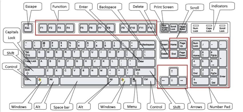
Using keyboard shortcuts can greatly increase your productivity, reduce repetitive strain, and help keep you focused. For example, highlighting text with the keyboard and pressing Ctrl + C is much faster than taking your hand from the keyboard, highlighting the text using the mouse, clicking copy from the file menu, and then putting your hand back in place on the keyboard. Below are our top 10 keyboard shortcuts we recommend everyone memorize and use.

Ctrl + C or Ctrl + Insert

Both Ctrl + C and Ctrl + Insert will copy the highlighted text or selected item.

Ctrl + V or Shift + Insert

Both the Ctrl + V and Shift + Insert will paste the text or object that's in the clipboard.

Ctrl + Z and Ctrl + Y

Undo any change. For example, if you cut text, pressing this will undo it. This can also often be pressed multiple times to undo multiple changes. Pressing Ctrl + Y would redo the undo.

Ctrl + F

Pressing Ctrl + F opens the Find in any program. This includes your Internet browser to find text on the current page.

Alt + Tab or Ctrl + Tab

Quickly switch between open programs moving forward.
Tip: Press Ctrl + Tab to switch between tabs in a program.
Tip: Adding the Shift key to Alt + Tab or Ctrl + Tab will move backwards. For example, if you are pressing Alt + Tab and pass the program you want to switch to, press Alt + Shift + Tab to move backwards to that program.
Tip: Windows Vista and 7 users can also press the Windows Key + Tab to switch through open programs in a full screenshot of the Window.

Ctrl + Back space and Ctrl + Left or Right arrow

Pressing Ctrl + Backspace will delete a full word at a time instead of a single character.
Holding down the Ctrl key while pressing the left or right arrow will move the cursor one word at a time instead of one character at a time. If you wanted to highlight one word at a time you can hold down Ctrl + Shift and then press the left or right arrow key to move one word at a time in that direction while highlighting each word.

Ctrl + S

While working on a document or other file in almost every program pressing Ctrl + Ssaves that file. This shortcut key should be used frequently anytime you're working on anything important.

Ctrl + Home or Ctrl + End

Ctrl + Home will move the cursor to the beginning of the document and Ctrl + Endwill move the cursor to the end of a document.

Ctrl + P

Open a print preview of the current page or document being viewed. For example, press Ctrl + P now to view a print preview of this page.

Page Up, Space bar, and Page Down

Pressing either the page up or page down key will move that page one page at a time in that direction. When browsing the Internet pressing the space bar also moves the page down one page at a time.
Tip: If you are using the space bar to go down one page at a time press the Shift key and space bar to go up one page at a time.


How do I remove computer memory in my computer?


If memory is already installed in your computer memory slots, some or all of it needs to be removed before additional memory can be added. Below are the steps on how to remove memory from your computer.
If the computer is not already opened, open the computer and locate the memory in the memory slots you want to remove.
Crucial memory scannerIf all your memory slots are occupied and you are not sure what memory to remove, use a third-party tool such as the onlineCrucial Memory scanner to display your memory information. The picture is an example of what the results of this memory scanner may show. As can be seen in the picture, the example computer has 8GB of memory with 2GB memory cards in each of the available slots. If you wanted to upgrade this to a total of 16GB of memory, you would remove all 2GB memory sticks and replace them with 4GB memory modules.
Once you've located the memory you want to remove from the computer you should notice two tabs on either side of the memory slot as shown in the picture below. Press each tab down and away from the memory slot. If done successfully, the memory should pop out and once both tabs are away from the memory module you can lift the memory out with no effort.

Installing a PC computer power supply

Before getting started

  1. Write down important information from the top or bottom of the power supply such as the Model Number, Serial Number and specifications (such as voltage...).
  2. Ensure you are familiar with ESD and its potential dangers.
  3. When physically installing the power supply, ensure the computer is off and the power plug is disconnected from the power supply.

Remove previous power supply

If you are replacing a power supply that is already in the computer, remove the power supply from the computer by first disconnecting the power supply from the motherboard and all other devices and then unscrewing the screws on the back of the power supply and possibly within the computer case.

Install power supply

Once no power supply is installed into the computer, place the new power supply into the computer and screw the screws into the back of the power supply. Most computer cases today also have a screw within the computer case; if present, also screw a screw into this hole.

Connect cables

Once the power supply has been physically installed into the case and is being held in the case, attach the power supply cable from the power supply to the motherboard. Next, connect each of the power connectors for the hard drive, cd drive, floppy drive and any other peripherals.

Installing a PC computer processor

Before getting started

  1. Write down important information from the of the processor such as the Model Number, Serial Number, and specifications.
  2. Ensure you are familiar with ESD and its potential dangers.
  3. When physically installing the processor, ensure the computer is off and that the power is disconnected.

Remove previous processor

If a processor is already installed in the computer it must be removed before a new processor can be added.
If the processor is a socket processor and has an attached heat sink, it must first be removed before the processor can be removed. Most socket heat sinks have a wire to supply power to the fan, first remove this wire. Next, you should notice clips on either side processor holding it in place. Pressing down on the larger end of the clip and then moving the clip away from the processor should release one end of the clip allowing for the heat sink to be removed.
Once the socket heat sink has been removed, if your processor is a ZIF processor, remove the socket processor by locating a small arm on one of the sides of the processor. This arm is a small metal bar. Moving this bar from a horizontal to a vertical position will release the processor.
If your processor is a LIF processor you need a processor and chip remove tool to remove the processor. If you are adding a new processor it is likely that this tool is included with the processor. If not, it can be purchased at a local computer shop or computer retail store. Place this tool between the processor and the socket and gently work the processor out of the socket, doing a little on each side of the processor at a time. When doing this, be careful not to bind or break any of the pins.
If your processor is a slot processor, the heat sink does not need to be removed and in most cases cannot be removed. To remove a slot processor, locate two tabs on either side of the processor. Move these slots to the outward position and the processor should be able to be removed by vertically pulling it out.

Install processor

Once no processor is currently installed in the computer, follow the steps below for installing your processor.
Socket Processor
If you are installing a ZIF socket processor into the computer, begin first by moving the metal arm located on one of the sides of the socket to a vertical position. Next, examine the top of the processor that should have a small dot in one of the corners. This dot indicates where pin one is located on the bottom of the processor. Next, examine the socket on the motherboard; this socket should have a missing hole or should have a 1 indicating pin one. Position the processor so both pin1 and hole1 match and then place the processor down.
If properly positioned, now when moving the metal arm to the down or horizontal position it should firmly connect the processor.
If you are installing a LIF socket processor, first examine the top of the processor and locate pin one, located with a small white dot. Once pin one has been located, look at the socket and locate pin one on the socket on the motherboard. Pin one on the socket will be located by either looking for a missing hole on the socket itself or by looking for a small one next to one of the four corners.
Once the pins have been aligned properly, gently press the processor into the socket until it is firmly attached.
Slot Processor
Finally, if you are installing a slot processor, first move the tabs on either side of the support brackets to the outward position. Next, install the processor by pressing the processor into the slot. Once successfully installed into the brackets the two tabs should snap into place.

Apply heat compound

It is recommended if your computer processor is a 200MHz or higher and does not already contain a processor heat sink that a heat compound or grease be applied between the processor and heat sink to help distribute the heat away from the processor.

Attach heat sink

Once the processor has been successfully installed and the heat compound applied, attach the computer heat sink to the processor.
Note: Users who have a socket processor, when attaching the heat sink clip, ensure not to scratch the motherboard with the clip. Also, when attaching the heat sink bracket to the plastic clip, be careful because if too much pressure is applied the plastic clip, it will break.
My computer beeps on power on!

Computer POST and beep codes

The computer power-on self-test (POST) tests the computer to make sure it meets the necessary system requirements and that all hardware is working properly before starting the remainder of the boot process. If the computer passes the POST the computer gives a single beep (with some computer BIOS manufacturers it may beep twice) as the computer starts and the computer will continue to start normally. However, if the computer fails the POST, the computer will either not beep at all or will generate a beep code, which tells the user the source of the problem.

AMI BIOS beep codes

Below are the AMI BIOS Beep codes that can occur. However, because of the wide variety of different computer manufacturers with this BIOS, the beep codes may vary.
Beep CodeDescriptions
1 shortDRAM refresh failure
2 shortParity circuit failure
3 shortBase 64K RAM failure
4 shortSystem timer failure
5 shortProcess failure
6 shortKeyboard controller Gate A20 error
7 shortVirtual mode exception error
8 shortDisplay memory Read/Write test failure
9 shortROM BIOS checksum failure
10 shortCMOS shutdown Read/Write error
11 shortCache Memory error
1 long, 3 shortConventional/Extended memory failure
1 long, 8 shortDisplay/Retrace test failed

AWARD BIOS beep codes

Below are Award BIOS Beep codes that can occur. However, because of the wide variety of different computer manufacturers with this BIOS, the beep codes may vary.
Beep CodeDescription
1 long, 2 shortIndicates a video error has occurred and the BIOS cannot initialize the video screen to display any additional information
Any other beep(s)RAM problem.
If any other correctable hardware issues is found the BIOS displays a message.

IBM BIOS beep codes

Below are general IBM BIOS Beep codes that can occur. However, because of the wide variety of models shipping with this BIOS, the beep codes may vary.
Beep CodeDescription
No BeepsNo Power, Loose Card, or Short.
1 Short BeepNormal POST, computer is ok.
2 Short BeepPOST error, review screen for error code.
Continuous BeepNo Power, Loose Card, or Short.
Repeating Short BeepNo Power, Loose Card, or Short.
One Long and one Short BeepMotherboard issue.
One Long and Two Short BeepsVideo (Mono/CGA Display Circuitry) issue.
One Long and Three Short Beeps.Video (EGA) Display Circuitry.
Three Long BeepsKeyboard or Keyboard card error.
One Beep, Blank or Incorrect DisplayVideo Display Circuitry.

Macintosh startup tones

TonesError
Error Tone. (two sets of different tones)Problem with logic board or SCSI bus.
Startup tone, drive spins, no videoProblem with video controller.
Powers on, no tone.Logic board problem.
High Tone, four higher tones.Problem with SIMM.

Phoenix BIOS beep codes

Below are the beep codes for Phoenix BIOS Q3.07 OR 4.X
Beep CodeDescription and what to check
1-1-1-3Verify Real Mode.
1-1-2-1Get CPU Type.
1-1-2-3Initialize system hardware.
1-1-3-1Initialize chipset registers with initial POST values.
1-1-3-2Set in POST flag.
1-1-3-3Initialize CPU registers.
1-1-4-1Initialize cache to initial POST values.
1-1-4-3Initialize I/O.
1-2-1-1Initialize Power Management.
1-2-1-2Load alternate registers with initial POST values.
1-2-1-3Jump to UserPatch0.
1-2-2-1Initialize keyboard controller.
1-2-2-3BIOS ROM checksum.
1-2-3-18254 timer initialization.
1-2-3-38237 DMA controller initialization.
1-2-4-1Reset Programmable Interrupt Controller.
1-3-1-1Test DRAM refresh.
1-3-1-3Test 8742 Keyboard Controller.
1-3-2-1Set ES segment to register to 4 GB.
1-3-3-128 Autosize DRAM.
1-3-3-3Clear 512K base RAM.
1-3-4-1Test 512 base address lines.
1-3-4-3Test 512K base memory.
1-4-1-3Test CPU bus-clock frequency.
1-4-2-4Reinitialize the chipset.
1-4-3-1Shadow system BIOS ROM.
1-4-3-2Reinitialize the cache.
1-4-3-3Autosize cache.
1-4-4-1Configure advanced chipset registers.
1-4-4-2Load alternate registers with CMOS values.
2-1-1-1Set Initial CPU speed.
2-1-1-3Initialize interrupt vectors.
2-1-2-1Initialize BIOS interrupts.
2-1-2-3Check ROM copyright notice.
2-1-2-4Initialize manager for PCI Options ROMs.
2-1-3-1Check video configuration against CMOS.
2-1-3-2Initialize PCI bus and devices.
2-1-3-3Initialize all video adapters in system.
2-1-4-1Shadow video BIOS ROM.
2-1-4-3Display copyright notice.
2-2-1-1Display CPU Type and speed.
2-2-1-3Test keyboard.
2-2-2-1Set key click if enabled.
2-2-2-356 Enable keyboard.
2-2-3-1Test for unexpected interrupts.
2-2-3-3Display prompt Press F2 to enter SETUP.
2-2-4-1Test RAM between 512 and 640k.
2-3-1-1Test expanded memory.
2-3-1-3Test extended memory address lines.
2-3-2-1Jump to UserPatch1.
2-3-2-3Configure advanced cache registers.
2-3-3-1Enable external and CPU caches.
2-3-3-3Display external cache size.
2-3-4-1Display shadow message.
2-3-4-3Display non-disposable segments.
2-4-1-1Display error messages.
2-4-1-3Check for configuration errors.
2-4-2-1Test real-time clock.
2-4-2-3Check for keyboard errors
2-4-4-1Set up hardware interrupts vectors.
2-4-4-3Test coprocessor if present.
3-1-1-1Disable onboard I/O ports.
3-1-1-3Detect and install external RS232 ports.
3-1-2-1Detect and install external parallel ports.
3-1-2-3Re-initialize onboard I/O ports.
3-1-3-1Initialize BIOS Data Area.
3-1-3-3Initialize Extended BIOS Data Area.
3-1-4-1Initialize floppy controller.
3-2-1-1Initialize hard disk controller.
3-2-1-2Initialize local bus hard disk controller.
3-2-1-3Jump to UserPatch2.
3-2-2-1Disable A20 address line.
3-2-2-3Clear huge ES segment register.
3-2-3-1Search for option ROMs.
3-2-3-3Shadow option ROMs.
3-2-4-1Set up Power Management.
3-2-4-3Enable hardware interrupts.
3-3-1-1Set time of day.
3-3-1-3Check key lock.
3-3-3-1Erase F2 prompt.
3-3-3-3Scan for F2 key stroke.
3-3-4-1Enter SETUP.
3-3-4-3Clear in POST flag.
3-4-1-1Check for errors
3-4-1-3POST done - prepare to boot operating system.
3-4-2-1One beep.
3-4-2-3Check password (optional).
3-4-3-1Clear global descriptor table.
3-4-4-1Clear parity checkers.
3-4-4-3Clear screen (optional).
3-4-4-4Check virus and backup reminders.
4-1-1-1Try to boot with INT 19.
4-2-1-1Interrupt handler error.
4-2-1-3Unknown interrupt error.
4-2-2-1Pending interrupt error.
4-2-2-3Initialize option ROM error.
4-2-3-1Shutdown error.
4-2-3-3Extended Block Move.
4-2-4-1Shutdown 10 error.
4-3-1-3Initialize the chipset.
4-3-1-4Initialize refresh counter.
4-3-2-1Check for Forced Flash.
4-3-2-2Check HW status of ROM.
4-3-2-3BIOS ROM is OK.
4-3-2-4Do a complete RAM test.
4-3-3-1Do OEM initialization.
4-3-3-2Initialize interrupt controller.
4-3-3-3Read in bootstrap code.
4-3-3-4Initialize all vectors.
4-3-4-1Boot the Flash program.
4-3-4-2Initialize the boot device.
4-3-4-3Boot code was read OK.